Follow Us

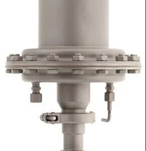
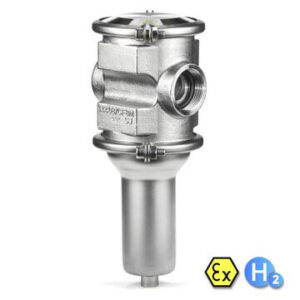
Pneumatic controller for continuous and discontinuous
pressure control of gases and steam.
High dynamic and control quality
• External or manual set point setting
• Compact and simple design of valve as well as of controller
• Lowest possible weight
• Meets the requirements of TA-Luft 2021
Connections:
P supply air
X actual value (pressure to
be controlled)
M pressure gauge (if required)
W air supply value
A exit to valve actuator
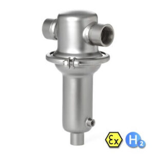
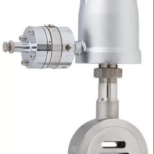
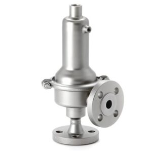
Valve
Body design
wafer-type construction, body
Dimensions acc. DIN EN 558-1 series 20
for flanges acc. DIN EN 1092-1 form B
more versions see data-sheet 8042-GS3
Nominal sizes DN 15 up to DN 150
Nominal pressure (acc. DIN 2401) PN 40 (fitting for PN 10-40)
Fluid temperature -10°C up to +230°C
Ambient temperature -15°C up to +60°C
Flange gaskets
(customer side) DIN EN 1514-1 or ANSI B16.21 in the respective nominal pressure rating
Leakage Disc pair
Carbon-stainless steel
Disc pair
SFC
Disc pair
STN 2
% of Kvs < 0,0001 < 0,0005 < 0,001
IEC 60534-4 IV-S1 IV-S1 IV
EN 12266-1 E F F
Marking ATEX non electric II 2G Ex h IIC T6…T1 X Gb
II 2D Ex h IIIC 85°C…350°C X Db
Packing leakage ISO FE – BH – CC3 – SSA0 – t (-40°C / +350 °C) – PN40 – ISO 15848-1
Controller
Control pressure ranges
0,05 – 1 bar (remote operation)
0,5 – 6 bar (remote operation)
0,5 – 2,5 bar (manual operation)
Supply pressure 4 – 6 bar
Temperature range for
diaphragm system 60 °C, maximum
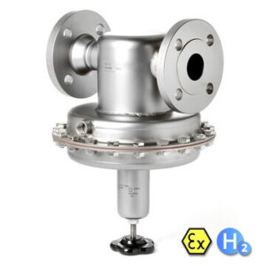
Manotherm is actively involved in most industry sectors including pharmaceutical, food, water, power generation, chemical, semiconductor, mining, HVAC, oil, and gas.
PRL Register number 1319WB
Quick Links
CONTACT US